de gb
de gb

Modern Sensors – A Challenge For The Lens


Trends of modern sensor development

In order to increase the resolution of sensors the pixel size is reduced from generation to generation. Meanwhile pixel sizes in the range of 2.5-3µ are standard for high quality imaging sensors. The resolution is also increased by a larger sensor area. For a long time 1“ sensors (16 mm diagonal) were considered large for C-Mount cameras. Nowadays even 1.3“ sensors with a diagonal of more than 20 mm are used. The smaller the pixels and the larger the sensor get, the more critical the pixel microlenses for the lens design is. The spectral sensitivity range is enhanced, requiring an optimized color correction of the lens.

Typical Sensors - examples

Sony IMX253  (12.4 Mpix)
Pixels: 4112 x 3008
Pixel Size: 3.45µ x 3.45µ
Sensor Diagonal: 17.6 mm
Nyquist Frequency: 145lp/mm
2/3 of Nyquist:  97lp/mm    


On Semi XGS20000  (20.3 Mpix)
Pixels: 4500 x 4500
Pixel Size: 3.2µ x 3.2µ
Sensor Diagonal: 20.4 mm
Nyquist Frequency: 156lp/mm
2/3 of Nyquist: 104lp/mm

Sony IMX530  (24.5 Mpix)
Pixels: 5328 x 4608
Pixel Size: 2.74µ x 2.74µ
Sensor Diagonal: 19.3 mm
Nyquist Frequency: 182lp/mm
2/3 of Nyquist: 122lp/mm


Teledyne Emerald 36M
Pixels: 6144 x 6144
Pixel Size: 2,5µ x 2,5µ
Sensor Diagonal: 21.7 mm
Nyquist Frequency: 200 lp/mm
2/3 of Nyquist: 133lp/mm
 

When object structures close to the Nyquist frequency are imaged, the sensor information might not represent the truth:

Limiting sensor resolution

The same object can cause totally different information on the sensor when structures close or over the Nyquist frequency are resolved (e.g. Moiree).


Pixel Size - required MTF
In order to have enough resolution for the pixel size but to avoid spurious resolution, the following rule of thumb can be applied: The MTF of the lens at 2/3 of the Nyquist frequency should be in the range of about 30%.

MTF = Modulation Transfer Function   (simply said the contrast of b/w line pairs)


Lens performance - theoretical MTF
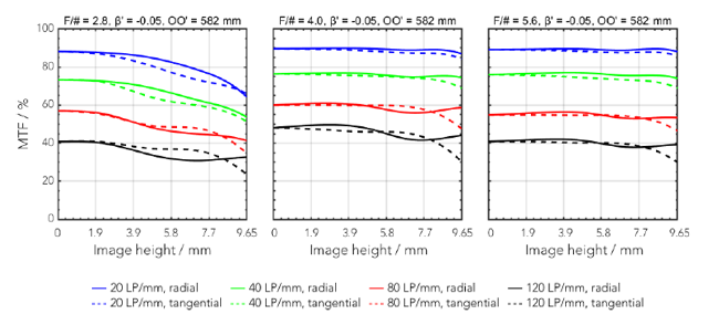
Polychromatic diffraction MTF of a lens for high resolution 1.2“ sensors 

MTF chart MTF chart lens

Technical data sheets for optical lenses are not governed by standards. Therefore it is very difficult to compare data from different manufacturers. And the difference between theoretical data and real lens performance can be huge.

  • Geometric MTF may show significant higher values then the more practical polychromatic diffraction MTF.
  • A limited spectral range or a centered weighting leads to higher MTF values.
  • TV distortion typically shows significant lower values than geometric distortion.
  • f/# and magnification are important parameters and need to be shown.
  • Real lens performance may differ significantly from theoretical data if the lens manufacturer can not realize the required manufacturing tolerances.
     

Lens performance - as it should be
A very even resolution performance over the whole sensor area with a maximum difference of one resolution group on the same radius. 

Performance of a lens which is not well centered and therefore shows strong performance variation over the image circle. Such a lens would not pass our 100% quality test.

Lens performance
Limiting sensor resolution

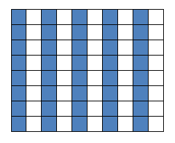
Limiting Sensor Resolution (Nyquist Frequency)

The limit is reached when a dark and a bright line fill 2 rows of pixels. Nyquist Frequency (linepairs/mm) = 1000 / (2 x pixel size (µm))
 

Sensor micro lenses - Angular sensitivity of sensors (datasheet)

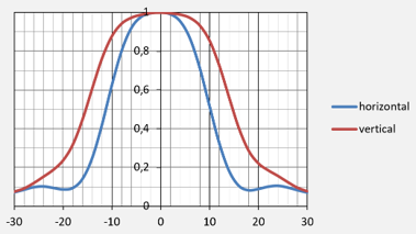
Nowadays the angular sensitivity of sensors is very often specified in the sensor data sheet – usually by a curve showing the angular response in relation to the angle of the incoming light.

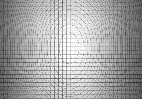
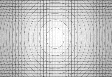
This is an example of a sensor with different sensitivities in horizontal and vertical direction resulting in shaded sides. There are also sensors available with equal sensitivties in both directions showing a concenric shading.

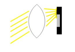
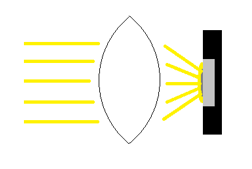
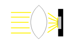
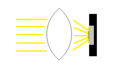
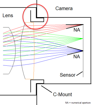
Most modern sensors are equipped with micro lenses on each pixel in order to increase quantum efficiency. But these micro lenses may cause that light under a certain angle is not projected onto the active pixel area.
 

Angular sensitivity
  • Pixel at sensor edge
  • Large CRA (chief ray angle)
  • Light misses active area (grey)
     
Angular sensitivity
  • Pixel at sensor center
  • CRA = 0°
  • light hits active area (grey)
     

In order to minimize the shading effect special lenses are required which are optimized for the sensor characteristics (Anti Shading Lenses). This often requires additional, larger lens elements and a complex mechanical design.

Anti shading lens
  • Pixel at sensor edge
  • Very low CRA
  • Light hits active area (grey)
     
Anti shading lens
  • Pixel at sensor center
  • CRA = 0°
  • light hits active area (grey)
     
Relative angular response

Relative angular response


Standard lens diagram

Standard lens


Anti shading lens diagram

Anti shading lens

Konsequences of micro lenses
Micro lenses...

  • limit the NA and so the F-number of a lens
  • may require a light fall-off by lens design towards the edges
  • require a large last lens element
  • may cause a complicated mechanical lens design
     

Variation of spectral sensitivity  

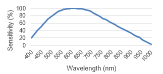
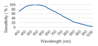
  • Actual sensors show more spectral diversity than former models – often with an increased sensitivity towards blue
  • Lenses need to be designed for a broader spectral range
  • More lens elements and/or special glasses are required for an optimized color correction of the lens

Spectral Sensitivity - Sensor 1

Spectral sensitivity

Spectral Sensitivity - Sensor 2

Spectral sensitivity
Micro lenses


Finally the good news

  • The increasing sensor size in combination with a reduced pixel size sets new requirements for the lens design and manufacturing
  • Lenses can be theoretically designed so that the high resolution of modern sensors is fully usable.
  • It is a challenge to transfer the theoretical performance into built lenses without sacrificing the performance. 
  • Some optical companies accept the challenge and are able to deliver high performance lenses which really utilize the sensor capabilities.


Get in Touch

Please do not hesitate to contact us if you have any questions. Our dedicated team is here to help you every step of the way.
Whether you need assistance with product selection, technical specifications, or general inquiries.

Jos. Schneider Optische Werke GmbH
Ringstraße 132
55543 Bad Kreuznach | Germany

Tel: +49 (0) 671 601 205
isales(at)schneiderkreuznach.com
Contact form